
SV Unladen Swallow's DC Electrical System
**** Disclaimer **** We are not Marine Electrical Engineers - we are not certified and anything we describe here is not intended to be used as reference material for your own work. Please do your own home work and better yet hire someone who does this for a living!
An Introduction
DC stands for Direct Current. Think batteries - your car battery, cell phone, laptop computer, flash light etc. Generally batteries provide power at very small voltages and must be used with other batteries to get to a usable voltage for electrical or electronic devices. That's why you generally use 2 or 4 AAA or AA batteries in a device. A Car battery is actually made up of multiple "batteries" or "cells" to get to 12 VDC. There are also 6 VDC batteries - like you might find in a golf cart.
Most of the electrical system found on boats like ours is designed to operate at 12 VDC. They generally have a set of large 12VDC lead acid or maybe AGM style batteries to provide this power. They also have starter batteries for any internal combustion engine on board.
Our boat had 3 12 VDC and 8 6VDC batteries onboard when we bought her. 2 of the 12 VDC batteries where the starter batteries for the GenSet and the Main Motor, while the 3rd helped power the anchor windless (more about that later). The 8 6 VDC golf cart batteries where arranged in 3 parallel strings of 2 batteries wired in Series (to make 12 VDC). Ok that sounds complex, but think of it as 3 large 12 VDC batteries that become one massive 12 VDC Battery.
Like I have stated before, this boat has already circumnavigated. Over the course of those 10+ years, the previous owner worked hard to improve and repair the boat with what he had in some pretty remote places. Additionally, once he found a workable solution, he seldom went back and made it “right”. As such, when it came to the DC system on the boat, as he was presented with the need to power a new thing, he often reached for the closest wire that was hot and had capacity to power that new thing. Additionally the original DC panel was full. He’d long since used the remaining spaces for spare breakers. Finally, when this boat was made, even though he had it built with the express purpose of going cruising, Beneteau was building these boats primarily for RACING. As such the factory electrical systems were not designed to support a cruising boat’s electrical needs. He had to make do with what was there.
DC Electrical Refit - 2021
So what we found that created cause for concern was a significant amount of power being consumed on the boat that was not controllable by the DC switch/ breaker panel.
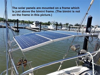
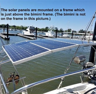
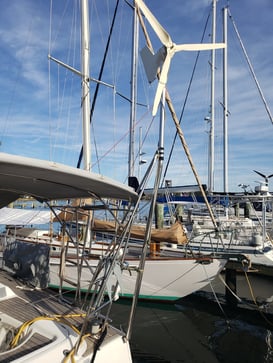
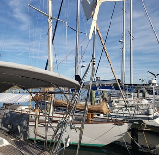
We also knew the 6 circa 2006 solar panels on the back of the boat were just crying to be updated. Finally, We also inherited a KISS wind generator. On a good day this could produce about 400W.
What we learned was that the compressors for both the refrigerator and the freezer had low voltage protects – in other words they would shut down if the voltage feeding them dropped too low. We lost 2 freezers full of food to this.
The original battery configuration for the boat was 8 -6VDC golf cart lead acid batteries arranged in a 12VDC configuration. While this was OK to hold things overnight, it was really too limited for the boat and required help from the GenSet or the main engine almost daily – especially being fed by the old 6x80W panels.
NOTE: Golf Cart batteries with heavy discharge/ charge cycling in warmer weather boil off water much more rapidly than regular car starter batteries. I highly recommend something like “Water my Battery” as a means of being able to easily keep up with the demand. Otherwise you may find yourself putting it off due to the difficulty of reaching all your batteries depending on how they are configured.
So it turns out golf cart batteries are great for slow discharge, they can not handle the needs of galley AC appliances. Also when we are underway, with the autopilot running, we discovered that the overall power draw really exceeded what they could sustainably do leading to the freezer defrosting.
Objectives
All DC power controlled by the main electrical panel
Improve solar to sustainably replenish the batteries
Accommodate the new electronics we wanted to install on the boat
Later we learned about the low voltage cut-off issues which was the final straw that pushed us to the Lithium upgrade in 2022.
The first step was to try to identify everything on the boat consuming DC power and where that power was being sourced.
NOTE: in Oct of 2022 when this is being drafted, I am still not sure we know everything. We certainly still don’t have a great idea of power consumption by load.
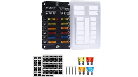
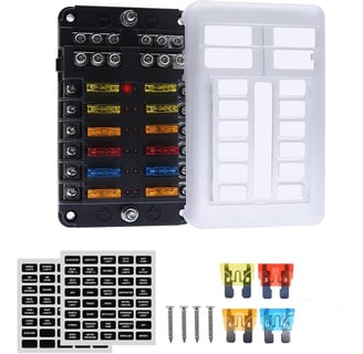
We then started to create a new circuit diagram for the boat. We quickly decided that sub-panels (a combination of switch panels and fuse blocks) were going to be required to include everything that wasn’t wired through the main panel.
NOTE: pulling new wire to the main panel area is very challenging as the routes through that part of the boat are basically full.
We then started to install the new subpanels and fuse blocks and lay in the new circuits to feed all the new electronics and some new lighting. The new solar arch was going to get a bunch of new lights, a camera etc. The ship’s electronics were getting several new devices. See the Electronics 2021 page.
We also did some homework on how to power the new consumer type electronics we wanted to install around a new Internet accessible ship’s network (both wired and WiFi). In that process we found that most of the devices were actually running off of either 5 or 12VDC and that the “wall worts” were just transformers to get back to that type of power. By cutting those AC devices off and using step down or step up transformers we were able to provide DC voltage at the right power level to power most of the consumer electronics. This allows us not to need the inverter to power most of those devices to include the ship’s PC, router and other supporting elements. We also acquired a bunch of 12VDC USB charging stations that are installed all over the boat to keep portable devices charged.
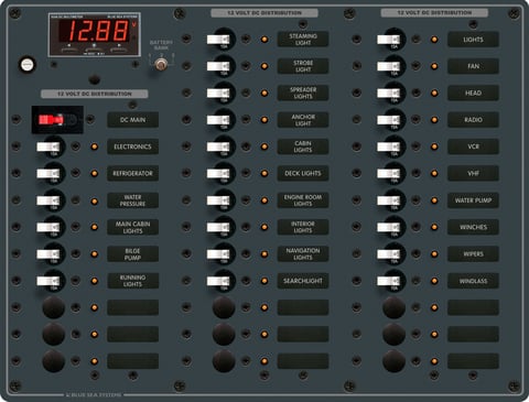
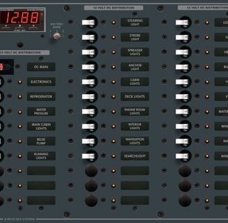
Finally we did acquire a new main DC panel that includes a master 100A breaker. It is large enough to accommodate future DC needs.
DC Electrical System updates - 2022
Diversified Marine Electronics – Annapolis, MD
PKYS – Annapolis, MD
Power on a boat that has as much electronics and supporting our Scuba diving is a different beast than the normal cruising boat. We started out with 800Ah of lead acid batteries as the house bank. They were not up to the task of even 1 day of reliable power while underway. This has led to our refrigeration/freezer compressors shutting down and frozen food defrosting. We had also had difficulties operating the kitchen AC appliances that involved heating elements. The Lead Acid batteries simply weren’t able to keep up with high loads over short periods of time.
We were told by many that the answer was Lithium batteries. The Victron Ecosystem is highly integrated, smart and provided everything we needed so we worked with David at Diversified Marine Services in Annapolis to design our system.
Lithium is really dangerous if it is not installed properly. If you are considering upgrading to Lithium, PLEASE, PLEASE work with someone actually trained in its use and by the OEM for the products you decide you want to use. DO NOT RELY solely on the work and design we have here. Please get a real trained Electrical Engineer to help you and the University of You Tube is not the answer.
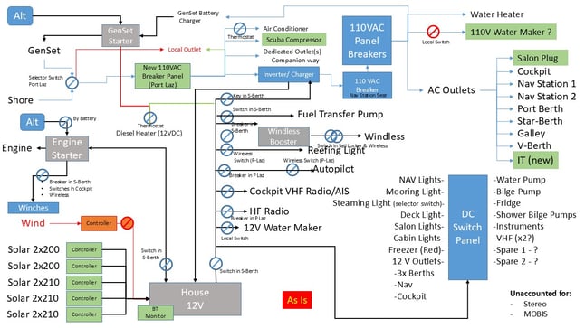
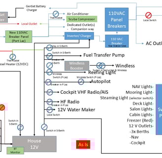
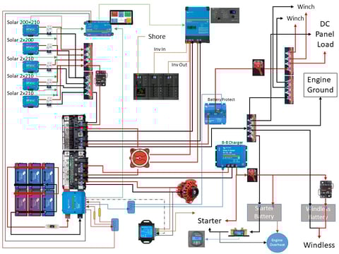
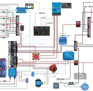
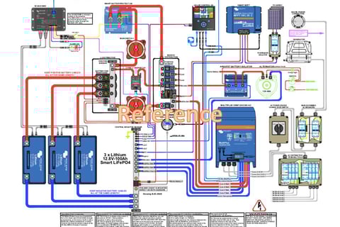
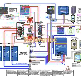
The below diagram is the logical diagram of the electrical system on SV Unladen Swallow.
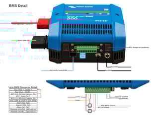
The above graphic shows the wiring we used for the BMS. Note: if we had not configured the batteries as one group of parallel batteries with a single Pos/Neg lead, we would have brought the battery leads into a Lynx distributer on these posts. The circuits coming off the green terminals on the side are the control circuits for OK to charge and OK to discharge. The lines marked Cerbo provide the power to run the cerbo control unit. There is also an electronic switch that can be used to start a GenSet or something similar.
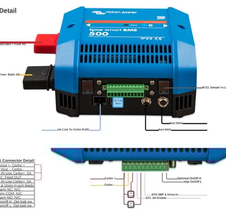
This diagram was provided by Victron as a reference system. It’s a bit dated as some of the parts and pieces have been upgraded by Victron. Specifically, it does not include any of the Lynx technology so the BMS shown has been replaced and the primary bussing was replaced by Lynx.
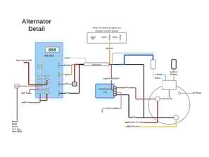
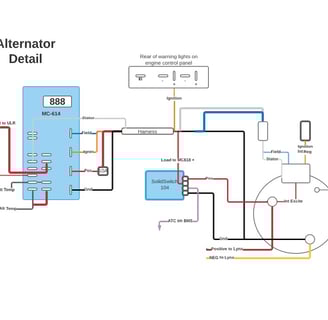
This diagram is how the upgraded Balmar Alternator is wired. This is still a bit of a work in progress. The external regulator is a bit dated, but the engineers swear by it. There is a 3 char LCD that provides the internal interface. There is also a PC interface that may be worth purchasing because you will want to be able to see the display while the alternator is running to diagnose and monitor it. We are going to install one and see how things go.
The power requirements to run the scuba compressor are significant. 30-32Amps running on 110VAC. That’s over 300 amps in 12VDC. In order to support this kind of load, we had to go to a 5KVW Inverter Charger and the primary wiring is 04 gauge. This is wire as thick as my thumb. It is very difficult to work with given its bend radius. It is also very expensive – we paid $500 for 25′ of Red and 25′ of Black colored wire.
The system is designed so all of the loads are now controlled on a single circuit. All of the charging inputs are also taken in on the Lynx via fused circuits.
The electric winches have given us some issues which led us to discover that the primary electric winch was eating itself leading to much higher power draw. More to follow as we have purchased a new winch that is a very different technology and we have high hopes for it once, we get it installed.
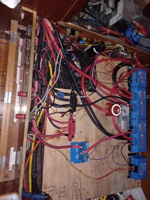
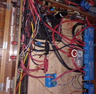
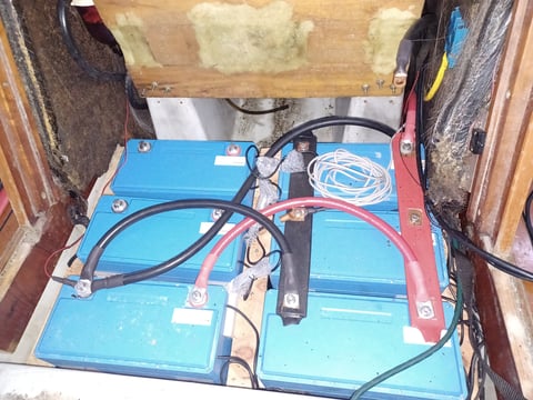
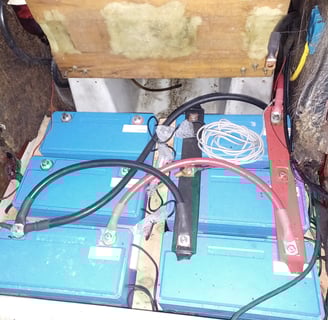
The above picture is definitely not the work of a trained electrical installer but it did take me the better part of a full week of uninstalling and then re-installing the new Victron based bus. The plywood provides a fixed mounting surface above the Port diesel tank for everything on the main bus.
In this picture, the BMS is the small box at the top, the 2 boxes in the middle are the primary bus – each of the lines has a mega fuse sized to the power expected to traverse that line. The big switch in the middle is used to isolate the Inverter/Charger. The small box at the bottom of the Lynx is the DC-to-DC charger to keep the starter battery charged. The other blue box is the battery protect. All of the DC load – other than the Inverter/Charger – goes through this box.
What’s not shown at the far left of this picture are the original battery cut off switches. The switch for the house battery needed to be completely cleaned off of all of the extra circuits that bypassed the main panel and now actually does control every load on the boat. The starter battery switch is also now clean, with the piggy back loads re-homed to where they belonged in the overall power architecture.
The other part of the upgrade is new switch panel at the helm to control a couple of new or re-homed devices.
2024 Update
The Cerbo GX has taken on a much greater role in the overall system. Check Out the dedicated Cerbo GX page for a detailed explanation of its function and how it’s wired into the larger Victron ecosystem and other functions on the boat.
DC Electrical Updates - 2023
The biggest change is to how we activate the Balmar Alternator. As originally wired, it was always on when the motor was running. This was creating a number of issues and for the most part our solar was more than enough to keep up with our power needs. When we had the motor running, we generally needed the power available for propulsion. A 150 Amp Alternator actually draws quite a bit of power to operate and that power was coming at the expense of propulsion and was causing coolant temp spikes at inconvenient times as it would cycle on and off as the batteries reached 100% and then would drain slightly and the regulator would decide to turn the alternator back off.
As we discussed the issue, we really decided that the alternator was there to replace the GenSet and that we didn't need it active all the time. In fact we only needed it operational for brief periods after several days of low solar output. We really wanted to treat the main engine like a GenSet or a Propulsive motor, generally not both.
So looking deeper into the capabilities of the Alternator Regulator, we noticed that it had a 12VDC input that was the initialization and powered the regulator. The simple answer was to put a switch on this input. With the switch off, the regulator was not powered and as a result, the alternator was not producing power. If we wanted the alternator's output, turning the switch on would power the regulator and everything would work as designed.
This solution has worked well.
DC Electrical Updates - 2024
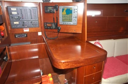
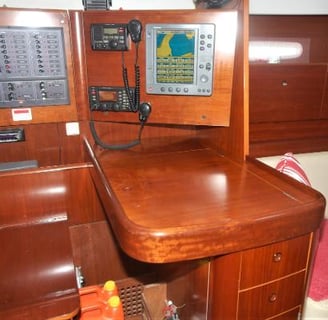
The big update in 2024 is the rewiring of the main electrical panels as a result of the Navigation Station area rebuild.