
Electronics found on SV Unladen Swallow
Ok this area is where I tend to geek out - Academically and Professionally I am a software engineer and a closet electrical engineer. For most of my adult life I worked with computers and electronics and generally viewed that technology as a way to improve my productivity and quality of life. I brought that "bias" to the boat.
Most boat owners and specifically sailors do not have that background. In fact they generally view electronics with distain and something else to break making their life more difficult.
I reject that point of view. A modern cruising sailboat is a very complex environment requiring constant attention to keep up with systems status, navigate, communicate and find entertainment. With Starlink now available the ability to be connected is now routine. To stay in the error of a compass and paper charts and SSB radio seems to be nostalgic and unnecessary. Are those skills (compass, sextant, paper charts) worthwhile - yes, but to ignore GPS, electronic charts and monitoring as unreliable is also not realistic. A balance is needed.
What we chose to do was take a boat that we felt we were working for and flip the environment enough so that we could at least work with the boat and eventually have the systems on the boat start to work for us.
So a summary of what the boat was equipped with when we bought the boat:
Raymarine was the primary manufacturer of the navigation and sailing instruments on the boat. These all dated back to the boats initial outfitting in 2004.
There was a new Garmin RADAR and an associated Garmin chart plotter - the new RADAR was incompatible with the old Raymarine Chartplotter.
There was a Cockpit VHF Radio, and in the Salon there was a another VFH and SSB HF Radio.
There was a TV Antenna and a few other novel bits and pieces.
Electronics 2021
**** Disclaimer **** We are not certified marine electronics engineers and have no formal training in Raymarine or Garmin Electronics and although we are formally trained in TCP/IP networking, we are not trained or certified in either NMEA 0183 or NMEA 2000. Everything we describe below and in future iterations is the result of research, consultation and a healthy amount of trial and error. Much of what we are describing below is changed or replaced in future years. If this really matters to you, hire a certified expert or be prepared to do a lot of research and your own journey of trial and error. *****
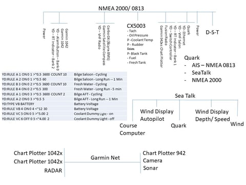
Part 1 – Exchange data between Sea Talk NG, NMEA 0183, NMEA 2000 and Garmin Net
It is now Jan 2025 and much has changed as I am reworking the entire web site as we have changed hosting providers and web authoring solutions. I want to address a few things before we get into what we did. In Jan of 2021, Starlink was not yet available. We were working to make the boat smarter and better connected to suite our lifestyle. Most of what we describe below ended up being very good solutions and as we prepare to start again with a new boat, we will likely retain much of the same technology to include maybe the original hardware which we salvaged from the boat.
Chart Potters
The Garmin chart plotters provide the gateway between Garmin Net and NMEA 2000. The two new helm plotters are our primary instruments while we’re underway. They can be turned around so we can see them while we’re in the lounge area of the cockpit.
Retire Ray Marine MFD–this was the original chart plotter at the Nav station on the boat. We were able to sell it at a consignment shop. We moved the original helm chart plotter, which is a touch screen, to the Nav station.
Quark Electronics – QK-A034
This device is the heart of being able to pass data between 3 of the 4 data networks on the boat – Sea Talk (Legacy Raymarine), NMEA-0183 and finally NMEA 2000. The AIS NMEA-0183 data is integrated here also.
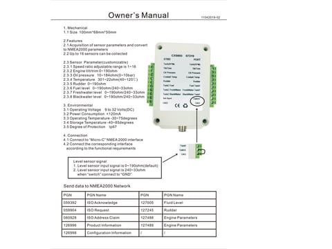
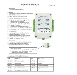
MARS – CX5003
This device is supposed to be able to ingest the analog signals of sensors from 2 engines as well as 3 sets of tanks (Black, Fresh, Fuel) and output those readings as NMEA 2000 messages. The tanks (2xFresh Water & 2x Diesel) are working fine but the Engine sensor signals are not being interpreted correctly. Since this device offers minimal configuration options, we are looking for an alternative to support the main engine. This is a NMEA 2000 device. The image to the right is literally the owners manual.
Spoiler alert - cheap Chinese stuff - it either works or it doesn't. Changing the engine RPM DIP Switches while it's powered bricks it. There are better albeit more expensive solutions out there.
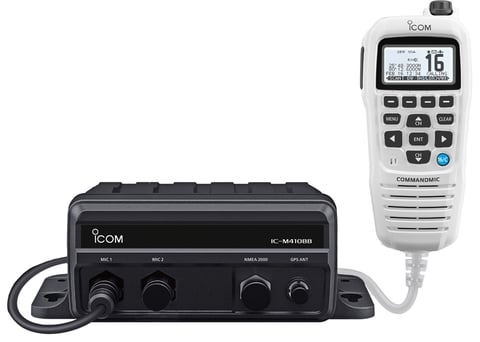
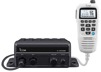
ICOM Black Box VHF for Helm
The original Cockpit radio (which included our AIS transponder) had been out in the elements long enough that the electronics had corroded to the point of being unusable. We chose to replace it with an ICOM black box which put the radio below out of the elements with a multifunction mic head in the cockpit. The antenna for this is mounted on the Solar Array arch. This is a 2way NMEA 0183 device.
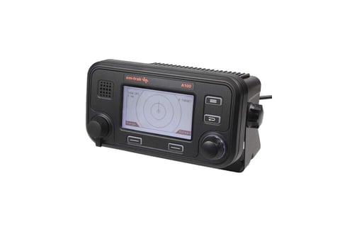
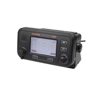
Class A AIS – EM-TRAK A100
We decided to use a Class A AIS as a separate box. This is a Transceiver that will show up on all commercial vessels as well as on internet based tracking services like Marine Traffic. Being seen by commercial vessels and being able to pull their information while underway provides visibility and eases communication because we can call each other on the radio by vessel name. The device also includes a proximity alarm to bring your attention to the fact that there is a vessel which may intersect your course. You can find us by looking for a US Flagged Vessel called “Unladen Swallow”.
Ship’s PC & Plex Media Server
Living on a cruising boat means that you are not always going to be connected. Since Brownie and I both like to have music playing in the background and have been known to like to watch classic TV and movies, we have built ourselves a PLEX server with an extensive media collection (10+ TB of music, TV and Movies).
The PC is a Dell solidstate box that will also support tracking of boat parameters and help with network and systems configuration and monitoring.


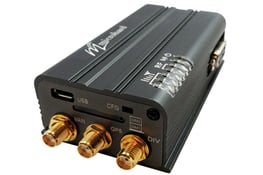
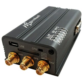
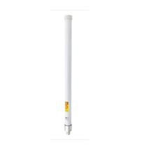
MicroHard – Bullet Cat12 – Cellular Modem & High Gain Antenna
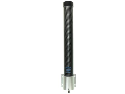
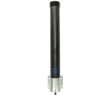
We have paired a MicroHard BulletCat 12 cellular modem with a Proxicast high gain MIMO cellular antenna mounted on the mast to provide the primary Internet gateway for the boat. So far we have been about to pickup streaming quality data as much as 10 miles off shore.
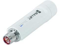
WiFi Bridge – Ubiquiti – Bullet
The bullet is our WiFi bridge. Should we find ourselves where we want to piggyback on someone else’s WiFi but do not want to rehome the devices on the boat, we can use this in place of the Cellular Modem to provide our internet. This device is POE.


Smart TV
OK so we like watching video based entertainment. We repurposed one of the smart TV’s from the house when we downsized everything and it’s now hanging on the large bulkhead in the salon. It’s one of the few electronics items that still requires AC power. Because it’s smart (it’s a ROKU) based device, it supports all the streaming apps natively to include accessing the PLEX media server.
Forward Looking SONAR
The forward looking SONAR allows us to see the depth in front of the boat. It helps us at slow speeds in shallow water to stop before we run out of water and ground the boat. This device operates on Garmin Net.
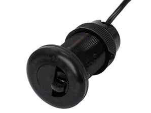
AirMar DST-810
This transducer replaced 2 old transducers to make room for the Sonar. This device provides us with Depth, Speed through the water as well as water temperature. It is a NMEA 2000 device.
When this was wrapped up we had moved most of our control and reporting to the Garmin Chart Plotters. The fresh water and fuel tank levels were now visible via the chart plotter (the previous owner had never put a tank level sensor on the aux fuel tank). Also most of the Sea Talk based data was now visible on the Chart plotters. This meant that we no longer needed to look at the wind instrument control heads which were not mounted in a convenient place. We also had depth, temp and water speed on the chart plotters.
The only thing that was not working well was neither the AIS nor the Ray Marine course computer connected GPS were being shared across to the Garmin chart plotters. Fortunately, the chart plotters had built in GPS antennas.
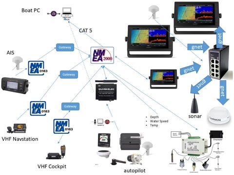
This would be our configuration throughout the Bahamas and back up the East Coast. The below picture is the logical diagram
For Part 2 of this story, see the 2022 Electronics page.
Ubiquiti Bullet (WiFi Bridge)
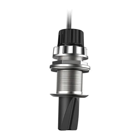
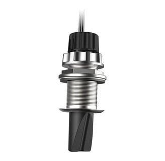
Antenna for the Bullet
AirMar DST 810
Garmin Sonar
Bullet Cat12
High Gain Antenna
EM-TRAK A100
ICOM Black Box VHF Radio
CX5003 manual
QK-A034
Refit - Phase 2 - Electronics 2022
Now that we had moved the boat in the general direction of the 21st century, we were ready to make the electronics on the boat start working for us. Our vision was always to have sufficient automation onboard to provide monitoring of critical functions as well as engine monitoring that would allow us to preemptively do maintenance on the motor before it quit working at inopportune times.
To accomplish those rather lofty goals – remember this boat was built in 2002 and the previous owner never spent a dime he didn’t need to…. we set about the following projects:
Shared common GPS throughout all the electronics devices
Critical system monitoring: Bilge pumps, water pump
Engine monitoring – enhance the dummy light only configuration
Oil Pressure sensor
Coolant Temp sensor
Fuel Vacuum pressure
Raw water flow
Unified Alarm Architecture – There were 5 or 6 different things that could sound an alarm and they all sounded similar
A course computer that would actually follow a course or wind angle vs just a compass heading
New ICOM VHF for Nav Station – this is related to goal 1 – shared GPS. The old radio wasn’t communicating on the data backbone – this was an inexpensive problem to resolve. Someone bought the old radio as a backup on his center console fishing boat.
Yacht Devices:
NMEA 0183 Gateways for each VHF Radio
NMEA 2000 Ethernet Gateway
Electronic Switch controller
2 Run Indicators
Alarm Button
We’re not going to bother with pictures of the yacht device products. They are not real interesting, but the Yacht Device ecosystem is very interesting and we have high hopes for it as we learn to program it and make it sing. For now this architecture will provide the bilge pump and fresh water pump monitoring as well as monitoring for the engine dummy light circuits. The Alarm button should become the unified alarm architecture for the whole boat. The electronic switch controller will allow us to use the chart plotters to turn on and off key circuits – like deck lights – away from the physical switch they are tied to. Finally, the ethernet gateway will allow us to use either the ship’s PC or a laptop to interact with the boat’s electronics to monitor, control and configure the overall settings or even operate some of the devices.
Engine Controls and Gauges upgrade
SV Unladen Swallow has a Volvo-Penta D2-55A diesel motor as its auxiliary propulsion. This motor is a traditional – think pre-electronics -motor. In fact it’s actually a Perkins Diesel motor made in England. This is the same motor that was installed in tractors all over the world – just without the marine cooling loop. To that end, it is a very simple motor. The external monitoring consists of just an Oil Pressure sensor switch – tied to a dummy light; a coolant temperature sensor switch tied to a dummy light (which didn’t work due to corrosion – the previous owner fitted the engine with an after market temp sensor with a separate audible alarm); a warning light letting you know the glow plugs were on, and finally a starter battery voltage warning light. The previous owner had added an after market analog oil pressure gauge and an aftermarket fuel vacuum gauge to help monitor things. These were separate analog gauges visible from inside the boat by the companionway stairs.
There is a solution for the fuel vacuum sensor also, but at almost $300 it’s going to wait a while.
Victron EcoSystem
If you read through the DC System 2022 page, you will see that we settled on the Victron Ecosystem for our electrical power needs. As part of this environment, there is a NMEA 2000 interface available for the Victron Cerbo GX control module. This brings much of the power related sensor data onto the Chart Plotters. We have used this environment to host several temp sensors (Refrigerator, Freezer, Engine compartment). We are excited about the possibilities here, but the temperature data isn’t currently being shared so getting alarms due to higher than normal temps is still a work in progress.
Cameras
We have installed 2 of the 3 planned cameras for the boat – top of mast looking forward, stern looking back. The 3rd is a FLIR (Forward Looking Infrared) but it will wait until we have 8 spare BOAT units. Unfortunately we are having integration issues right now and the 2 installed cameras are not cooperating. More to follow when we have more time to troubleshoot. The mast camera is the important one as it will provide an unobstructed forward looking view for the watch stander.
The tachometer and Hobbs meter (engine hours) are also separate, after market gauges.
The CX5003 was capable of converting these sensors and more, so we set out to replace the dummy light switch sensors with discrete value sensors so we could actually track performance. This is a great goal but the version of the CX5003 we installed is dumber than the engine and matching the inputs up to what it is expecting is proving to be challenging. We are looking at alternatives and think we have one in the ActiSense EMU-1 but the programmable interface isn’t back in stock until after Jan 2023 – not much help right now. For now we are going to make do with what we have and when the ActiSense ecosystem is available again, we will re-evaluate.
Garmin MSC-10 Satellite Compass
This device is the heart of the new course computer and unified GPS for the boat. It should provide the missing data to allow us to set it and forget it. Can’t forget it, there are still plenty of things to run into or be run over by, but you get the point.
Starlink Dish
Starlink is now a thing finally. SpaceX appears to allow the RV version to operate off of private yachts. There is a marine rated version, but it is targeted at the MegaYacht, commercial marine industry based on price. We have it mounted and have a hack that will allow us to retire the Starlink router entirely (it really is just powering the dish) so we don’t need the inverter for it. We haven’t gotten that part to work quite yet, but will shortly and we will post the solution. The Starlink signal is being fed into the WAN port on our ship’s router and then shared with everything else through that common gateway.
Update post USVI passage. This was a total game changer. We had connectivity all the way with occasional interruptions likely due to the dynamic sea state. We were able to conduct real-time VOIP telephone calls and access everything online we wanted. We watched You Tube and Netflix and got weather, sent e-mails and texts. The Iridium subscription is going to be suspended as a result.
Iridium-Go Hotspot
This is our highly reliable (and low bandwidth) offshore communications solution. It will allow us to get weather data for Predict Wind and send and receive short messages. It compliments the previously installed Garmin Montana which provides the InReach based GPS realtime tracking. We can also receive and send text messages and get some weather information there.
Post USVI update – This worked great as expected, but Starlink worked sufficiently well to make this an expensive redundancy. We will leave it installed, but it’s getting turned off.
Part 2 – After leaving Fairhaven Shipyard.
Course Computer
The old RayMarine course computer didn’t have all of the required inputs to allow it to follow a wind angle or a true course. Even with our upgrades, the data was not making it to the computer to be used. Time to retire it. We have a Garmin Reactor 40 that will be integrated before we leave Annapolis that will enable all of this and more and it will be controllable from the Chart Plotter and have a working remote. We are excited about the possibilities there. No more having to disturb whichever cat has nestled down on the watch stander to go adjust the heading on the autopilot head…..
Due to the delay in Moorhead City we were able to take physical custody of the unit earlier than we expected and tried to get it working prior to leaving for the USVI. Unfortunately, it had some pretty specific power requirements that I wasn’t able to account for on initial install, so it’s going to wait til I can relocated the power control box – the new device is actually 3 separate boxes – to a location closer to the Hydraulic ram motor.
Engine Monitoring – integration and tuning — pending CX5003 troubleshooting
Yacht Devices Tuning
The yacht device ecosystem is incredibly flexible, but there is some programming required. Unfortunately the “let’s see if this works easily” trial didn’t produce the results we hoped for. We will be taking a more measured approach over time where we build our knowledge and understanding step by step through experimentation. This is basic software debugging on a new system. Something we can handle, just need some time to work through it. We will publish our final programming rules later along with all the NMEA 2000 addressing etc so others can learn from our work.
New CX5003
I am still not a big fan of these devices. When they work, they are inexpensive and easy to setup – provided you match the inputs exactly with what’s expected. Otherwise there’s not configurability. There is a set of DIP switches that allow you to tune the RPM readout to your specific setup. I.e. pulley size ratio between the crank shaft and where ever you are taking your pulse rate from. Well after apparently damaging 2 of these units, we have discovered that changing the dip switches must be done with the unit unpowered. Otherwise it “breaks” every sensor input not in use as well as renders the RPM input unusable. We are going to wait on the RPM input til I find a better option. Unfortunately, the likely option is 6 times more expensive. more to follow
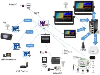
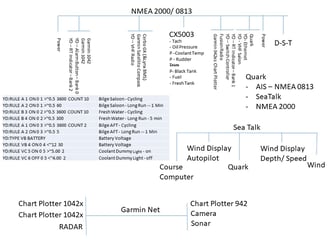
Final Architecture for 2022
When this is all said and done the architecture should look like the below picture.
Electronics - 2023
We did alot while in Secret Harbor and Curaçao and the details are on the Refit 2023 page.
Electronics - 2024
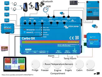
Cerbo GX Updates
The following is what was planned for the Cerbo GX updates during the Haul-out in 2024. Most of this was wired when Hurricane Beryl hit. Some of it had been tested, but everything to do with Node Red had been implemented.
The Victron Cerbo GX is the brains behind the Victron Ecosystem. It is actually a customized Raspberry PI running the Victron Venus OS.
The Cerbo GX is designed to also monitor/ manage up to 4 tanks (Fresh, Grey and /or Black), monitor up to 4 digital inputs (relay based triggers), up to 4 hardwired temperature sensors (LM335 temperature Sensor), USB based inputs (GPS, Bluetooth Temp Sensors) as well as managing the Victron ecosystem.
There is a tremendous amount of functionality built into this device and SV Unladen Swallow is using quite a bit of it. The diagram below shows how it is currently configured.

Cerbo GX Buses/ Protocols
VE.Direct is a point-to-point unbalanced serial connection where as VE.Can (aka CANbus) is a balanced (RS-485) multi-drop connection. I think VE.Direct came first in the Victron world.
VE-Direct requires a connection on Cerbo, etc. for every device and at most there are 3 ports. You can extend this by using a VE.Direct to USB adapter cable.
VE.Can is physically different from CANbus. VE.Can uses ethernet cabling, looping through each device. CANbus uses a unique connector with “taps” to go to each device. You can interconnect VE.Can to CANbus with the appropriate adapter. The entire network is terminated at both ends with a 120 ohm resistor. VE.Can/CANbus is limited to about 100 devices. VE.Can/CANbus operates at one of several baud rates and in the Victron world, this rate must be the same for all devices on the same port. Additional VE.Can ports can be added to Cerbo via a USB to CANbus adapter.
As best as I can tell – lots of opinions out there, but the bottom line appears to be the BMS.Can ports are intended to hook 3rd party BMS’s into the Victron environment. There are some mentions about Galvanic Isolation and specific protocols but it get pretty cryptic. Since my environment is all Victron devices, these ports appear to be superfluous.
VE.CAN Ports
Lynx BMS
The Lynx BMS connects to the Cerbo GX via the VE.Can bus
NMEA 2000 Interface
This is a special dongle connected to the 2nd VE.Can bus port.
This allows the Victron ecosystem data to be visible on the Garmin MFDs and also consume data generated from elsewhere in the N2K ecosystem (e.g. GPS)
VE.Bus Ports
Quattro (Inverter/ Charger)
This connects via the VE.Bus. It also connects to the external Digital Remote Console on the same bus. The bus must be terminated at each end (????)
BMS.CAN
not used
USB Interfaces
The Cerbo GX is configured with 3 USB ports – note Port 3 is power only and is intended to power the remote display.
Since we are using more than 2 USB devices, each port hosts a powered USB Hub
USB 1 – Hub 1 (This will be a powered hub – 5 VDC via a buck converter)
MMPT 1
MMPT 2
USB 2 – Hub 2 (This will be a powered hub – 5VDC via a buck converter)
External Bluetooth adapter
GPS Receiver
External Relay Bank
USB 3 – Power Only
Power the external Display
HDMI
This is the display output for the external Display
MicroSD Card
The Cerbo GX has some internal storage, but if the VRM connection is lost for more than a day or so, data is lost. A 128 GB microSD card holds several years worth of data and provides a backup to the cloud based VRM data.
Tank (1-4), Temperature (1-4), Digital Input (1-4)
The boat’s fresh water and fuel tank levels are integrated via the ActiSense analog to N2K converter. We may use one of these inputs to home the Black Water tank level at a future date.
The Temperature inputs use the LM335 temperature Sensor standard. This is a European standard and the US based standard is incompatible with it. The Ruuvi Bluetooth sensors provide a very capable alternative so the hardwired ports are not used.
The 4 digital inputs are generally intended to collect state data (on/off) from other systems to drive error conditions. At this point, this is the 3rd input alternative for this type of data. Given other alternatives, we likely won’t use these ports.
Relay 1
We are going to wire COM to ground and then use NO as the output to signal a general error condition (alarm) for the Cerbo GX to the master alarm panel
Relay 2
We are going to wire COM to ground and then use the NO as the output to signal a temperature alarm to the master alarm panel. Configuring this relay for temperature is a software setting. The Ruuvi Temp Sensors in the Refrigerator, Freezer and the Engels will feed this logic.
12 VDC
The Cerbo GX is going to take it’s power feed from the Lynx BMS AUX power port (+/ -)
WiFi and Bluetooth and RJ45 Ethernet
The Cerbo GX is configured to operate on the “Unladen Swallow” TCP/IP network on the boat. The “Unladen Swallow” network is hosted on an internal Router which hosts a VPN client so all “Unladen Swallow” network traffic flows through the VPN tunnel generally back to a USA based proxy.
Since the internal Bluetooth transceiver is known to be lower power, best practices are to add a USB based higher power Bluetooth transceiver. This makes working with the Victron Connect app on while onboard more reliable. It also enables better communication via bluetooth with other non-hardwired victron devices.
The RJ45 LAN port is not used at this time. The Cerbo GX cannot act as a router and will default to the RJ45 if connected. Normally this port would provide a direct connection to the GarminNet to support the Victron App on the Garmin MFDs. However, if this connection is used, the Cerbo GX cannot easily connect to the broader internet which is being accessed via the Cerbo Gx’s WiFi port. (There are people who have used static IP addressing and routing to make this work, but it’s a significant amount of work). Since the VRM connection is a priority and the Victron based digital data is made available to the N2K ecosystem which is available to the Garmin MFDs, this connection to GarminNet is not as useful.
Victron Remote Management (VRM)
The Cerbo GX will push data to Vitron’s data management and storage cloud solution called VRM via the WiFi connection through SV Unladen Swallow’s Starlink Internet. This will allow remote management and monitoring of the energy environment as well as other data points.
Signal K Server
This is the other part of the remote data aspect of the Cerbo GX server. Since the Cerbo has access to the N2K data feed, it can host a remote N2K feed to support Open CPN or other external data feeds.
Our big plans here are to make all of the data available to our Garmin MFDs available to remote devices (not on the boat) using something like Open CPN. This will allow us to share in “near real time” our chart plotter based information while we are underway. This will allow others to see what the boat is doing as we travel.
Node Red
This is the other component that is available with some reconfiguration of the Cerbo GX and loading the Large OS version of the Venus OS. The Node Red environment looks like it is a highly customizable programming and control environment that will allow us to interact with any parameter available in the N2K/ Victron/ Garmin ecosystem. It will then allow us to control external devices via USB based Relays. I have ordered a external non-Vitron device that contains 8 additional relays.
Some examples are found here
Relay switching (from the dashboard)
So the first project is:
Hot water with Excess Solar Power
This will hopefully allow us to do things like turn on the water heater when we have excess solar power. The basic idea is to trigger on battery State of charge combined with time of day. If the SOC is greater than say 98% and we are after 12 noon and before 5pm, then let’s use the excess solar capacity (the batteries are full) to power the electric hot water heater.
I will publish detailed instructions on how this works once it’s working.
Some additional software packages to extend our Cerbo GX Function:
GuiMods –
GUI MODS, or Graphic User Interface Modifications, are third-party software that allows users to customize the display of their Cerbo GX or other Venus GX device. GUI MODS can be used for:
Customizing the home screen
Tying up information in the display
Making additional SmartShunts appear on the front page of the display
Getting AC voltage information
Some advantages of GUI MODS include: More intuitive operation and Easy interaction.
Some disadvantages of GUI MODS include: A more crowded screen.
GUI MODS provides even more details in one screen, such as voltage, frequency, and amperage at both the source side (Shore) and the inverter output side. The enhanced Hub overview includes voltage, current, frequency, and input current limit values.
You can also check out this video:
Cerbo GX Logical and Physical Connections
Master Alarm Panel
The Following is what was planned for the Master Alarm Panel implementation. Everything was wired to the patch panel behind the Alarm panel but the Alarm Panel was not yet wired in and testing had not yet started.
Welcome to the world of too many alarms on a sailboat. When we bought the boat, there were 4 different piezo alarms on the boat that all sounded the same. That was really confusing. To add to the confusion we added a very extensive NMEA 2000 backbone and Garmin Net ecosystem. We now have more possible sources of alarms then anyone can possibly deal with.
To solve our confusing alarm environment, I ran across a Alarm Button from Yacht Devices and installed and configured it – combined with the Yacht Device Run Time Indicator, it offered a very robust monitoring solution. We could set a different alarm for each issue. Sounds great – BUT now we needed a cheat sheet to tell us what each sound stood for. Still not very effective. So although it sounded great, in principle, it really wasn’t a good solution.
On an aircraft or spacecraft there is a Master Alarm Panel. This panel has lots of buttons or LEDs all labeled and corresponding to a different error / Alarm condition. But it has a single sound for the alarm and then the ability to mute the alarm.

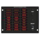
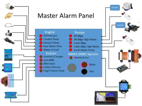

This is really appealing in our application. We have 16 unique systems that all generate ‘Alarm” signals. We also have all the digital based Garmin/ NMEA 2000 error conditions.
There are multiple ways for a system to raise an analog alarm but all boil down to a switch that closes a circuit relay passing either Ground (-) or 12VDC (+) along to a receiver.
Engine Sensors
The engine sensors are all ground based switches. We have 5 engine monitoring sensors. Their functionality overlaps a bit, but they all will alert us to the engine getting ready to overheat and self-destruct. We also have 3 NMEA 2000 based engine sensors that provide us discrete values for Oil Pressure, Coolant Temperature and finally Vacuum pressure level on the engine side of the Racor Filter (planned for Fall 2024). The 5 engine sensors form the basis of the Dummy Lights for the engine. We lost the dummy lights when we redid the Engine panel last year and have been anxious to get this functionality back. The Yacht Device Alarm button and Run Time Indicator could do some of what we wanted but this will be a more dummy proof solution.
Victron Ecosystem
The Victron devices are all “NC – COM – NO” relays so they will get setup to connect to ground. The Cerbo GX has 2 alarm relays – we are going to use one as a master alarm for the Cerbo GX Environment and the other will be tied to the temperature monitoring function. We have temp sensors (RUUVI) in the Fridge and Freezer to alert us if they go off line. Otherwise the Quattro (Inverter/ Charger), the Lynx BMS, and the Alternator regulator all have the ability to raise alarms if things are amiss. None of these alarm functions are currently configured/ integrated in our current environment so we are excited to have this new functionality.
Pumps (Bilges & Fresh Water)
The pumps are going to be a combination of High Water alarms – float switches that close a ground circuit and counter circuits to detect cycling. Finally the fresh water pump will run through an external timer circuit set to likely 5 minutes.
Garmin Net/ NMEA 2000 Digital Alarms
Finally for all of the digital based error / alarm conditions within the Garmin/ NMEA 2000 environment, we will grab an alarm output (+) on the Salon Chart Plotter. Because everything else is ground based, this one will go through an external relay to close a ground circuit. This one is going to be a bit of a work in progress as any alarm raised is going to have to be acknowledged twice (we think). The good news is the Master Alarm audible alarm will be louder than the chart plotter based alarm so we will get woken up easier – especially for Anchor Drag alarms.
Aqualarm Solution
The company Aqualarm is building the panel to spec for us. They specialize in alarm panels and are happy to customize to your needs. They also have several pre-built solutions for more basic requirements. They are adding a “Test” button to verify function of all circuits for us.
What to do with our Yacht Devices based alarm system?
Finally, we are not completely sure what to do with the Yacht Devices architecture yet. There are some functions in there we might wish to retain, but that will be post installation of this Master Alarm Panel.